Scantech International, a 3D laser scanning company in the UK, with over 15+ years of point cloud survey experience. With a vast amount of knowledge in this industry, we will like to show you the following:
Laser scanning is a technology for quickly capturing dimensions and shapes of complex structures and features.
Laser Scanners have been available for over 20 years but the first practical and “portable” laser scanner was the Cyrax scanner in 2002. This collected 1,200 points per second, took 20 minutes per scan and covered a field of view of 40° x 40°.
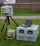
The portable Cyrax 2500 laser scanner weighing 20kg and the battery another 15kg – now used as a doorstop!
Since 2002 there have been many technological advances resulting in the latest Leica RTC 360 laser scanner which can collect 2m points per second, takes 30 seconds per scan and can take HDR colour photographs in another 60 seconds.
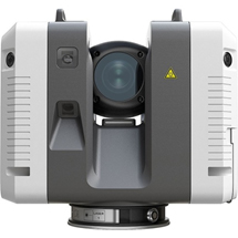
The latest RTC 360 laser scanner weighing just 5.35Kg and has a field of view of 360° x 300°
3D Laser Scanning is a non-contact, non-destructive technology that digitally captures the shape and dimensions of physical structures and objects using a line of sight laser light. Laser scanning uses a very rapid laser beam of up to 2 million points per second to scan the environment and capture a vast quantity of data from the surface of structures and objects in the form of a pointcloud. Each point has it’s own XYZ coordinate and is referenced to a fixed datum.
In other words, a 3D laser scanning survey or a Cloud Burst Survey is a way to capture a structure or an objects exact size and shape and represent this in the computer world as a digital 3-dimensional model.
3D laser scanners measure fine details and capture free-form shapes to quickly generate highly accurate point clouds. A 3D laser scanning survey is ideally suited to the measurement and inspection of contoured surfaces and complex geometries which require massive amounts of data for their accurate description and where doing this is impractical with the use of traditional measurement methods.
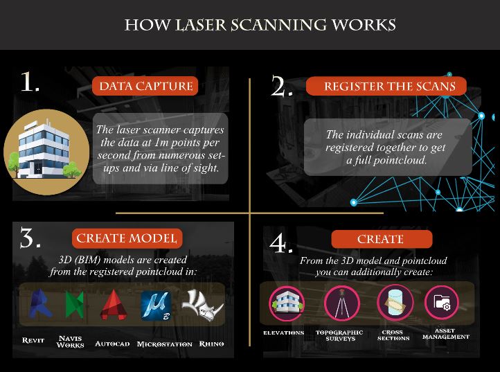
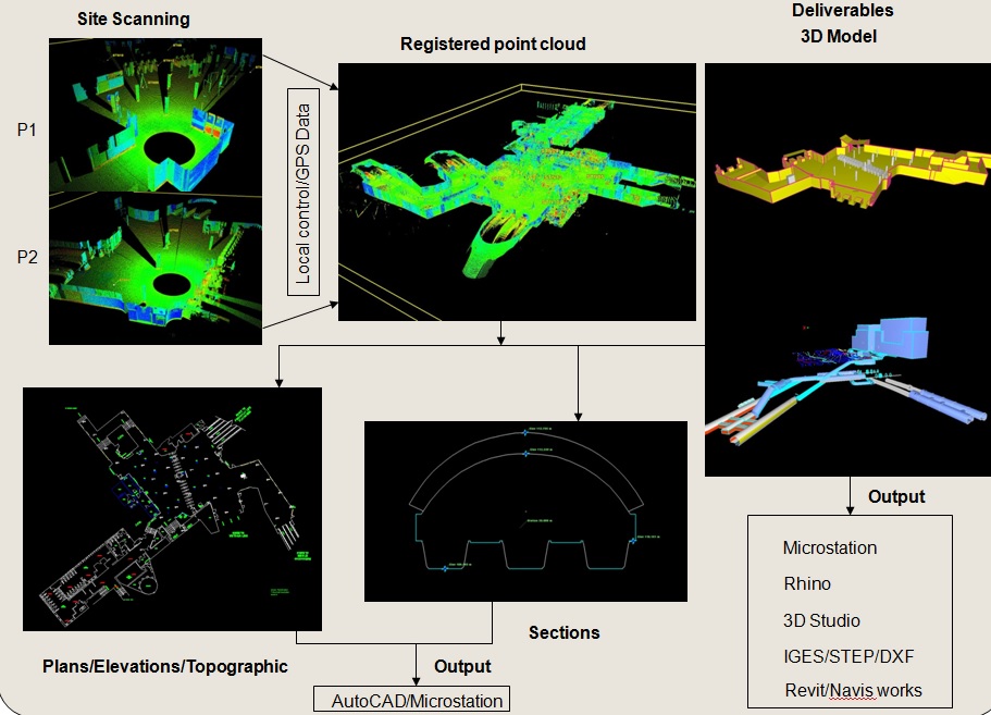
1) Site scanning – Numerous individual scans are taken.
2) Register all the individual scans together to create an overall pointcloud
3) Create the required deliverables from the overall point cloud.
As mentioned above the laser scanner sends out a laser beam at up to 2m pulses per seconds.
A spinning mirror reflects the beam onto the surface to be scanned where it is reflected back to the scanner. The RTC 360 utilises time of flight methodology.
This measures the time taken for the laser beam to reach the surface and reflect back to the scanner and using the speed of light calculates the distance. with its position in 3D space relative to the scanner datum and ultimately to any datum (i.e or geographical) set in post-processing.
Accuracy of 3D scan data and the resulting deliverables is extremely important, therefor we have developed our site scanning techniques to ensure that we achieve a ±5mm accuracy which is suitable for most engineering and architectural requirements.
To ensure that we achieve this level of accuracy, control points are surveyed in a traditional manner (using an EDM) and captured in the scans to ensure the accurate registration of the individual scans and the accuracy of the completed survey
There are many benefits from using laser scanning compared to more traditional survey methods and some of these are :
There are a variety of “names” for 3D laser scanning surveys including :
The cost of undertaking a 3D laser scanning survey is usually significantly less than a comparable traditional survey. The exact cost will depend on several factors including for example :
Similarly, the cost of producing a 3D CAD model will depend on the above factors plus
We can often price from drawings or for simple structures such as bridges we can quote over the phone. For more complex surveys a site visit is usually preferable.
The deliverables are the most important part of our survey. Getting the required deliverables, which the client can use has taken us years to learn and perfect.
Extracting data from a point cloud takes a lot of skill and it certainly helps to have an engineering background, which our technical office has. It requires numerous and usually very expensive pieces of software to create the required deliverable for our clients.
Here is a list of just some of the deliverables we can offer:
“If the deliverable you require isn’t on the list please get in contact and I am sure we can help”
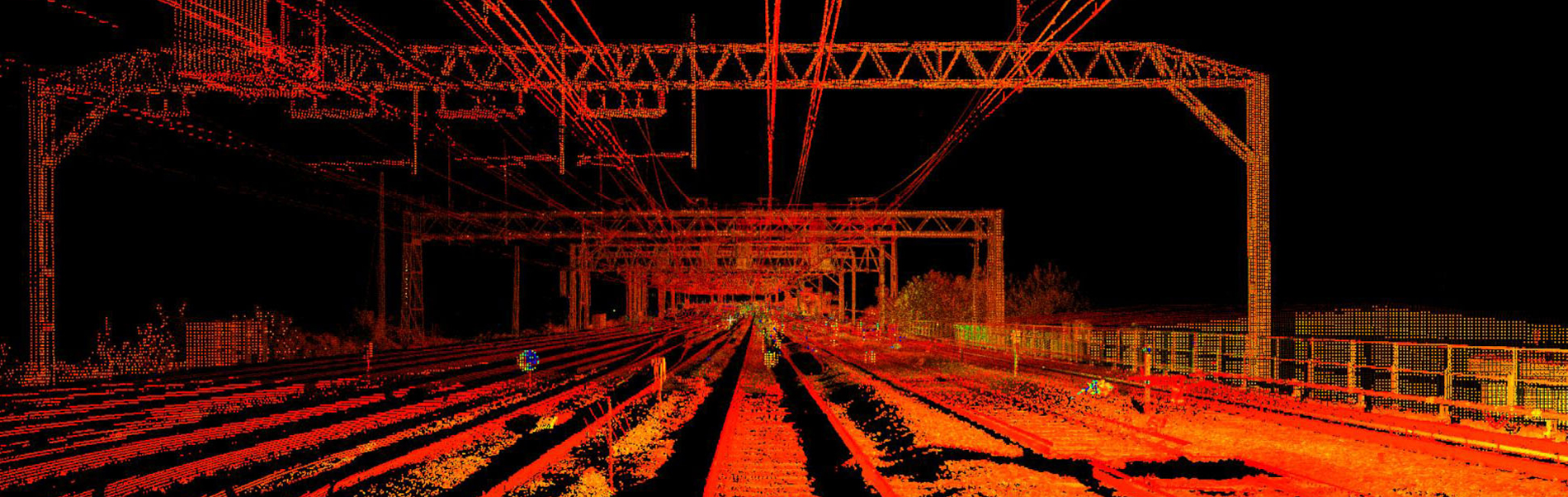
Each scan produces a point cloud relative to the position of the scanner. Numerous scans are taken from various positions and when registered or linked together form an overall 3D pointcloud of the structure/area.
The overall 3D point cloud data can be viewed in free software or can be input into various software formats to produce further deliverables such as 3D models, topographical drawings, sections etc. An example of an overall pointcloud is shown below.

3D models are produced from the registered 3D point clouds. A variety of software packages are available to produce the 3D models the most popular currently being Revit and AutoCAD.
The production of the 3D model is still a manual process and we have developed an expertise in this area especially with producing 3D models in Revit. This software is/was primarily a design tool for new build applications and it requires specialist applications to produce as-built 3D models of which the existing elements (walls, floors beams etc) are never quite square, straight or flat.
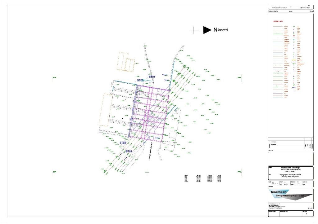
Topographical surveys are one of the traditional survey types and are often carried out with just an EDM instrument. Control points are installed at various locations around/in the area to be surveyed and are often orientated to OS coordinates. As the OS no longer maintain their benchmarks. The orientation to OS is normally carried out using RTK GPS.
Topographical surveys pick up all of the features including building outlines, drains, kerbs, manholes levels etc and we always confirm with our clients the features that they need as often we just get a request for a “topo survey”.
We also now use both the laser scanners and UAVs to carry out these surveys albeit they are allied to the use of the EDM. This equipment allows for the faster capture of both larger areas as well as more inaccessible areas.
Traditionally these surveys produced 2D plans (floor, ceiling and elevations etc). By utilising laser scanning we can produce 3D models in a number of formats including Revit. Revit is primarily a design tool for new builds and does not “like” surfaces that are not flat and/or straight.
The laser scanner picks up the true shape of these features and we have developed techniques over the last 7 years to accurately model these in Revit.
By using laser scanning again allied to control set out with an EDM, we can carry out these surveys up to 20 times faster than using an EDM alone. This is especially useful for older and dilapidated buildings where nothing tend to be straight or square.
We also utilise the UAV for capturing the roof details/features if access is not available or if it is not safe to do so. The resulting photographs can be converted to a pointcloud data and merged with the scan data to produce the overall point cloud of the building.
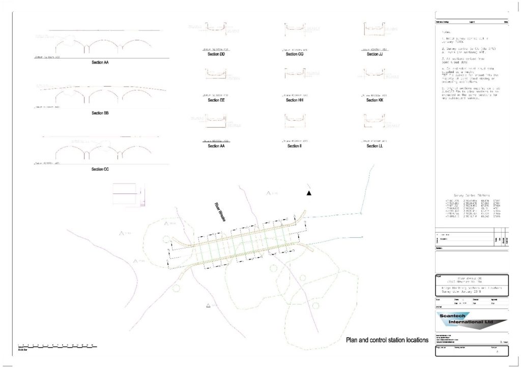
Sections can be produced from the registered point cloud data at any interval from 10mm to through the building/structure. These tend to be far more accurate than those obtained through surveys carried out purely with an EDM.
Similarly, building elevations are produced rapidly with the laser scanner as all of the relevant features are picked up including “swirl and twirl” type features.
For tunnel surveys, cross-sections can again be produced at any interval for gauging purposes as well as for condition monitoring. Defects and bulges are readily identified and any changes over time highlighted in subsequent surveys.
By utilising lighting and the camera feature on the new RTC scanner high resolution and definition colour images can also be produced for condition monitoring. See the Jetstream images section for more information on this.
After the structural elements of a building have been constructed we often are required to scan the area and produce a registered pointcloud. This is used by the M&E contractor who can input the point cloud into his design software and highlight any clashes from the design to the actual as-built structural elements.
This saves a significant cost associated with clashes that are only detected during the MEI construction for example when the ducting hits a column that is slightly out from the design position
The registered point cloud of an as-is process facility is often input into the design software during the design phase to highlight
We have utilised scan data on a number of jobs to measure both volume and area.
These include the following :
For the void and hidden shaft scanning, we use the C-ALS borehole scanner. This is inserted into a borehole and the resulting point cloud used to determine the volume of the void or shaft. This allowed the contractor to accurately order the correct amount of material to fill in the void or shaft.
For location 3D Surveys please see the following pages:

“We would like to thank you for your efforts delivering the topographic survey and 3D pointcloud survey for the 82 span, 1200m long Harringworth Viaduct recently.To complete the works for such a structure in the limited time available in the possessions was fantastic. We also appreciate your flexibility in rescheduling the works at short notice due to problems with the possession booking.We are now creating the elevations and sections for the viaduct and would like to thank you for the quality of your deliverables and your availability for ongoing discussions with our CAD team”.

“Morgan Sindall Professional Services were appointed by London Underground to provide a multi discipline design service for the upgrade of the ventilation system as part of the Victoria Line cooling the tube programme. The ventilation shafts are only available during a series of 4 hour engineering hour slots which requires 28 days notice before access is granted. The quality of the panoramic images provided by Scantech International Ltd allow the Client, Design Engineers and Contractor to constantly view and reference the complete infrastructure with out the need for repeat site visits, saving considerable time and money and maintaining confidence as the design develops and evolves “